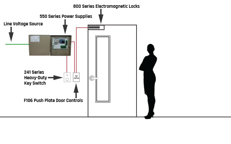
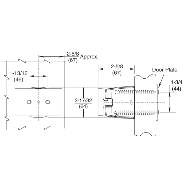
Electromagnetic Door Holder Wiring Diagram

Rixson Model 998 Electromagnetic Door Holder
Access Control Wiring Diagram Help Deltrexusa
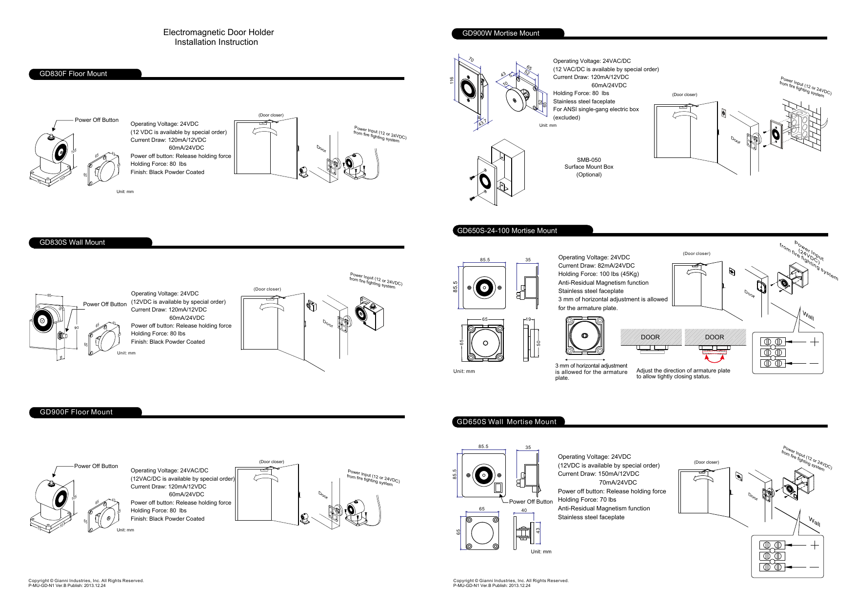
Electromagnetic Door Holder Installation Instruction Manualzz
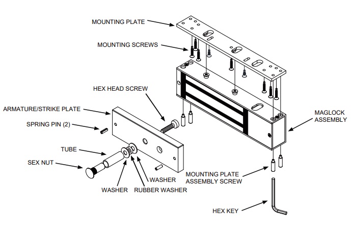
Door Holder I I P65 Dh Series Install

Abh 2100 Electromagnetic Recessed Wall Mount Door Holder

Magnetic Door Holders And Battery Backup With Facu Fire Alarms Online
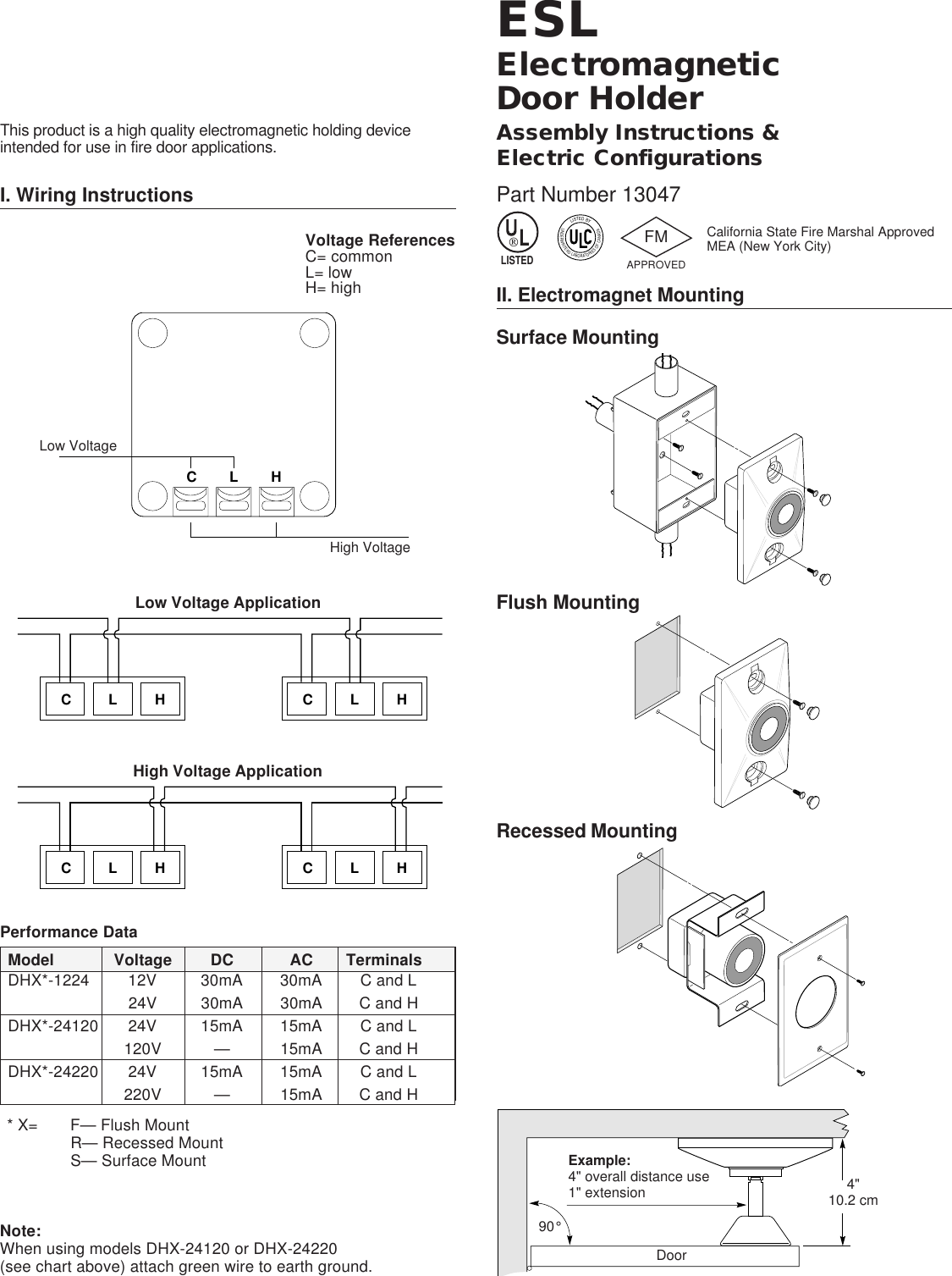
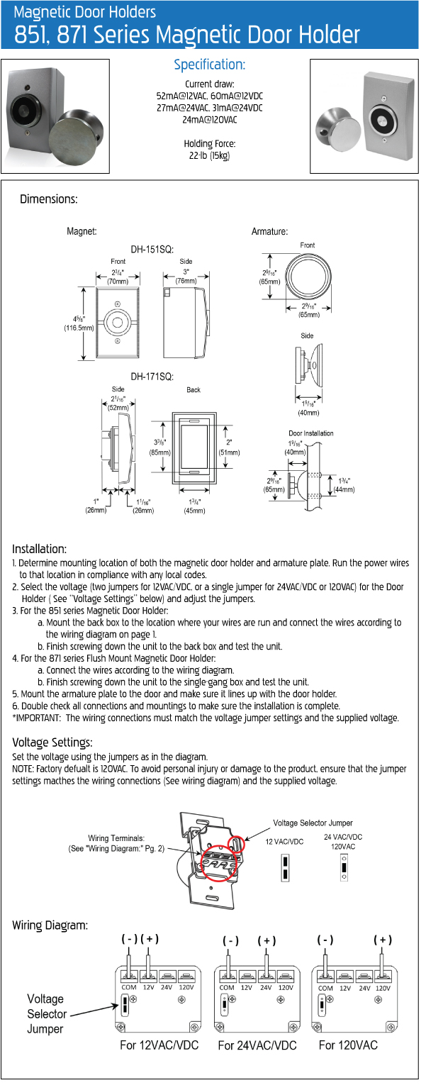
12 vdc 48 vdc current draw.
Electromagnetic door holder wiring diagram.

981m Electromagnetic Door Holders By Rixson Epivots Com
Https Www Abhmfg Com Content Documents 0000232 2600 Pdf
851 Surface Mount Deltrexusa Electronic Magnetic Door Security Parts

Smoke Detector Placement For Magnetic Door Holders Fire Alarms Online
Http Accesshardware Com Wp Content Uploads 2016 03 Abh 2300 Electromagnetic Door Holder Pdf

Magnetic Door Holder Wimatech Fire Fighting Partner
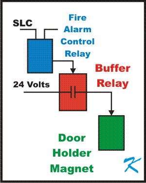
Why Install An Extra Relay For A Door Holder
.png)
Access Control Cables And Wiring Diagram Kisi
998 Electromagnetic Door Holders By Rixson Epivots Com

Rixson Fm998 Wall Mounted Tri Volt Electromagnetic Door Holder Wall Mounted

Home Improvement Electro Magnetic Door Holder Mdh101 Single Door Release Button 12 24vdc Black Home Garden Building Hardware

Magnetic Fire Door Holder Fire Alarm Heavy Duty Magnetic Door Catch For Sale Electromagnetic Door Holder Manufacturer From China 104658642
Seco Larm Magnetic Door Holder
993m High Hold Electromagnetic Door Holders By Rixson Epivots Com
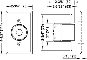
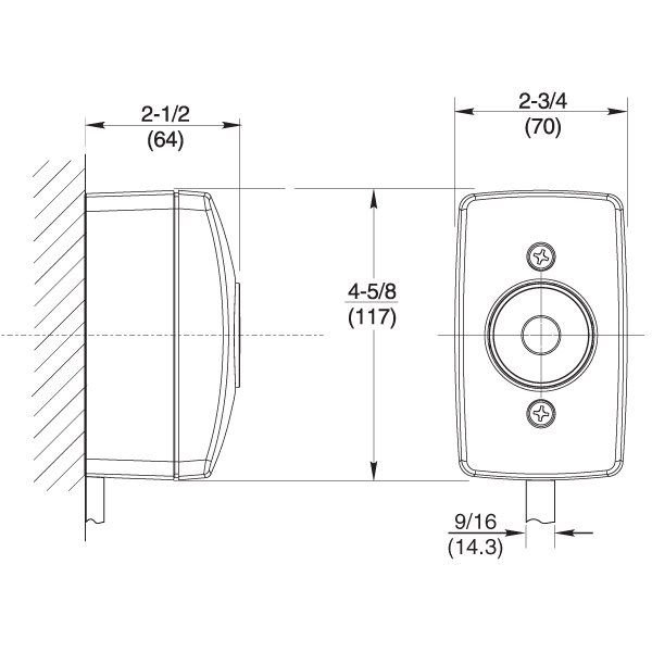
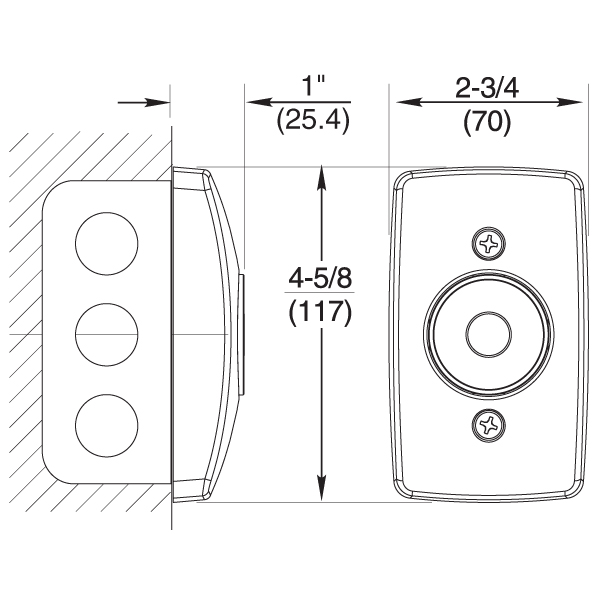
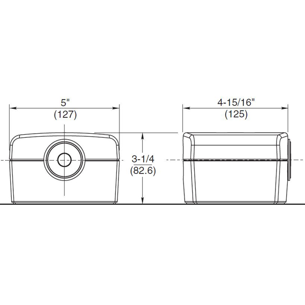
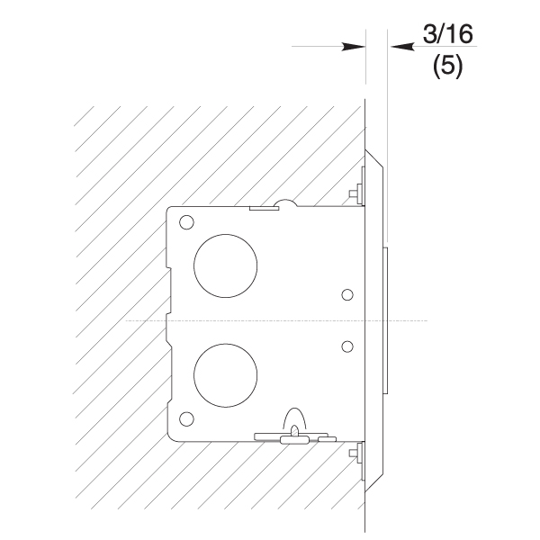
Door Holder Electro Magnetic Wall Mounted Model Se110 In The Hafele America Shop
996 Electromagnetic Door Holders By Rixson Epivots Com
997 Electromagnetic Door Holders By Rixson Epivots Com
980m Floor Mounted Electromagnetic Door Holders By Rixson Epivots Com
Https Encrypted Tbn0 Gstatic Com Images Q Tbn 3aand9gcrpvvkk6rhjo B7n2mcauinxoesiptfz Cu83kmui1irpzddzad Usqp Cau

Door Holder Electro Magnetic Wall Mounting Online At Hafele
990m Low Profile Electromagnetic Door Holders By Rixson Epivots Com

How To Wire A Maglock To The El2000 El2000ss El1ss Or El25 Telephone Entry System Youtube
Https Www Downloads Siemens Com Download Center Download A6v10238705

Abh 2510 Recessed Electro Magnetic Door Holder Surface Wall Mount Armature Thebuilderssupply Com
Source : pinterest.com
